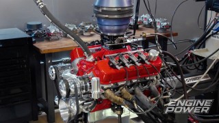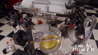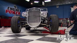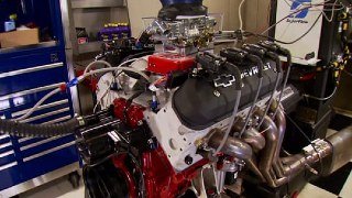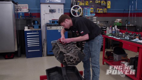
Modern 410ci Stroker Windsor with Custom EFI & Coil-Near-Plug Conversion - Part 1
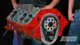
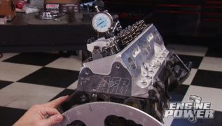
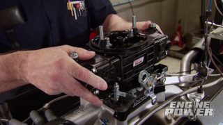
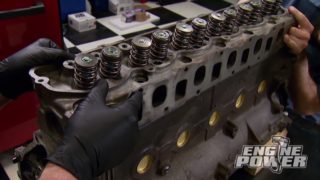
This Small Block Ford receives big power upgrades, including a forged rotating assembly, competition-ported cylinder heads, and a supremely accurate crank trigger system.
Season 9
Episode 14